Introduction:
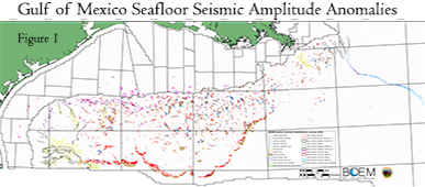 Since 1998, geoscientists at the Bureau of Ocean Energy Management (BOEM) have identified and mapped nearly 37,000 water bottom (seafloor) acoustic amplitude anomalies in the deep water northern Gulf of Mexico (GOM) using 3-D time-migrated seismic surveys. The purpose of this mapping program is to understand the distribution of natural hydrocarbon seeps and related benthic fauna (chemosynthetic and coral communities) in the GOM, and to characterize other seafloor features related to the geological framework of the seafloor. These areas show anomalously high or low acoustic amplitude response relative to typical background, with most areas having overlapping seismic coverage by two or more surveys. These results cover over 230,000 square kilometers of seismic data interpretation.
Mapping Methodology
The water bottom horizon was mapped over these surveys using hand-interpreted seed-lines and Schlumberger’s geophysical interpretation software GeoFrame’s automatic picking function to fill the gaps between. Next, the water bottom’s acoustic amplitude was extracted and displayed in plan view. Boundary polygons were drawn around areas with anomalously high-positive and low-positive amplitudes, as well as negative amplitudes (complete phase-reversal of the water bottom horizon). The amplitude maps were cross-checked with vertical seismic profiles to verify correctness in the autopicked interpretation. In vertical 3-D seismic profiles beneath most of the amplitude anomalies, blanking and/or visible fluid-migration pathways (e.g., vertical gas “chimneys” and faults) are often visible in the subsurface up to the water bottom. As through December 2016, BOEM, NOAA, industry contractors, and others have confirmed hundreds of the anomalies as hydrocarbon seeps and carbonate hard grounds through utilization of submersible, ROV, AUV, camera sled surveys, piston cores, trawls, and multibeam sonar identifying water column gas plumes. Figure 1 illustrates the total distribution of all 23 types of anomaly, however, not all anomalies nor anomaly types are visible in Figure 1 due to its scale and resolution. You will need to download the anomaly files to properly view all mapped features.
Anomaly Types:
Seep-Related Anomalies
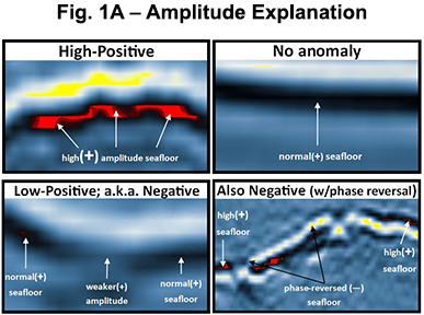
There are four classes of waterbottom anomalies interpreted to be caused by hydrocarbon seepage: 1) High-Positive, 2) Low-Positive/Negative, 3) Pockmarks, and 4) Water-Column Gas Plumes. What do we mean when we say high-positive, low-positive, and negative? Please see Figure 1A for a visual explanation.
High-Positive Class
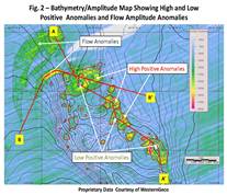
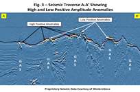
Exhibits a high-positive amplitude response relative to the background water bottom response, often shows hydrocarbon migration pathways on vertical seismic profiles. Most of these positive anomalies that have been directly investigated by submersible or ROV exhibit a slow to moderate rate of hydrocarbon seepage. The positive amplitude response on the seismic data has been found to be caused by the presence of authigenic carbonate hard grounds created by bacteria living off the hydrocarbon in the sediments at these seeps, producing calcium carbonate in the process. These hardgrounds provide suitable substrates for thriving chemosynthetic communities and both hard and soft coral types. High-Positive anomaly shapefiles are subdivided into 9 types:seep_anomaly_positives, the most abundant and colored red in Figure 1, are high-positive amplitude anomalies which have not yet been confirmed as seep-site hardgrounds – they are purely seismic interpretations. Due to the coarse vertical resolution of 3-D seismic (~30 feet), some of the high-positive anomalies visited by ROVs or submersibles have not had exposed authigenic carbonates at the seafloor due to soft sediment cover. There may be 28 feet of authigenic carbonate buried by 2 feet of hemipelagic mud, but the 3-D seismic amplitude will still show a strong high-positive anomaly (see Figure 1A, Figure 2, seafloor amplitude map and Figure 3, seismic profile A–A’).
- seep_anomaly_confirmed_organisms, dark red in Figure 1 are high-positive amplitude anomalies that have been confirmed to be hardgrounds with predominantly chemosynthetic communities, though most have corals to a minor extent. Confirmed via manned submersibles, ROVs, AUVs, camera sleds, trawls, and piston cores either by academia, government, or industry sponsored cruises.
- seep_anomaly_confirmed_corals, magenta in Figure 1 are high-positive amplitude anomalies that have been confirmed to be authigenic carbonates predominantly colonized by hard and/or soft corals, but have had chemosynthetic communities to a minor extent. These polygons also cover the rough boundaries of the shelf marine sanctuaries “Biobanks”.
- seep_anomaly_confirmed_hydrate are high-positive amplitude anomalies that have been confirmed to have significant seafloor natural gas hydrate exposures, but have always had active chemosynthetic communities near or adjacent to the hydrates. Many other sites in the GOM have been found to have hydrate exposures at the seafloor, but these sites are considered to be significant.
- seep_anomaly_positives_confirmed_oil are high-positive anomalies which have had direct observations of oil seepage from the seafloor by submersible, ROV, and/or analysis of piston cores, and all have had chemosynthetic and coral communities living on the carbonate hardgrounds.
- seep_anomaly_positives_possible_oil are high-positive anomalies located directly below sea surface oil slicks, or within one water depth’s distance. Though not directly observed to be seeping oil, we are calling these possible oil seeps due to their proximity to the slicks. They are likely to have chemosynthetic and coral communities living on the carbonate hardgrounds.
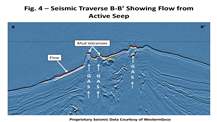 seep_anomaly_flows, blue with dotted infill in Figure 1, are high-positive amplitude anomalies interpreted to be flows of sediment out of high flux vent sites on steep slopes. They either 1) contained hydrocarbons and were subsequently partially lithified, 2) attracted chemosynthetic clams which consumed what hydrocarbon was available (and since they were not located at the active seep site, subsequently died), or 3) are made up of acoustically faster sediment (i.e., sand). The flows that have been visited by submersibles are often a combination of two or more of the above. Figure 2 shows flows (outlined in dark blue) that were partially lithified and had dead clam shells, both of which caused higher positive seismic response than the soft hemipelagic mud that dominates the deep water Gulf of Mexico. Figure 4 is a vertical seismic profile B-B’ showing the high amplitude (relatively a smooth surface) seafloor trending downslope from an active vent site; note the lack of migration pathways in the subsurface below the flow.
- seep_anomaly_confirmed_carbonate are former seep_anomaly_positives polygons. High-positive amplitude anomalies which have been surveyed with side-scan sonar and/or hi-res multibeam, and exhibit significant acoustic backscatter response at the seafloor, indicating clean carbonate hardgrounds with the potential to be suitable substrates for benthic communities. However, no direct visual observation of active communities has yet been performed.
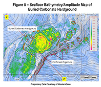
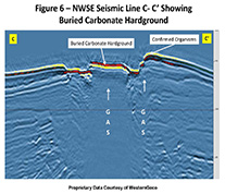
- seep_anomaly_confirmed_buried_carbonate are former seep_anomaly_positives polygons that the 3-D seismic vertical profiles show clear subsurface migration pathways to the seafloor, but subsequent visual investigations by manned submersible, ROV, or AUV (by government, academia, and/or industry) indicate that there are no exposed carbonates at the site, and/or remote sensing by multibeam or sidescan show no elevated acoustic backscatter, suggesting the presence of buried authigenic carbonates. Though clear seafloor indications of seepage such as bacterial mats (e.g., Beggiatoa) and/or brine seeps may be present, no suitable substrates for megafauna such as corals or chemosynthetic organisms (e.g., tubeworms, mussels, etc) such as hardgrounds are present. If shown to be buried by any of these methods above, the anomalies in question will be removed from the list of potential hard substrates suitable for benthic organisms and the 2000’ buffer to protect any communities are removed. Figure 5 is a depth bathymetry map in meters with an amplitude underlay showing a site (that was visited by the Alvin submersible) that displayed very high positive amplitudes on the seafloor over a large area in a graben, but had no exposed carbonate hardgrounds and only seep related bacterial mats and brine. Figure 6 is a vertical seismic C-C’profile illustrating the clear vertical migration route of hydrocarbons to the seafloor (i.e., “gas chimney”). This polygon has been reclassified as a “buried carbonate”. The Alvin investigated the slope and top of the eastern- bounding fault of the graben and found active seepage and chemosynthetic communities; the elevated seafloor there was apparently exposed to enough ocean currents to clean off sediments and expose the carbonates.
- Low-Positive/Negative Class
In the same style as Class 1 High-Positive, the Low-Positive/Negative class name also reflects the nature of the water bottom seismic horizon (green polygons in Figure 1). This class of anomalies exhibit acoustically slower response than that of typical hemipelagic mud of the GOM. It is subdivided into 5 types:- seep_anomaly_negatives, tiny green dots and circles in Figure 1, show an anomalously low-positive amplitude response on seismic compared to the typical hemipelagic muds. The most active and dynamic of this type exhibit a negative amplitude response, or acoustic trough, at the seafloor, resulting from a total phase reversal of the seafloor’s typical positive acoustic impedance. These areas have been observed to have rapid hydrocarbon flux, often with sediment and brine being expelled with the hydrocarbons (see Figure 1A, Figure 2, seafloor amplitude map and Figure 3, NW-SE seismic profile A-A’).
- seep_anomaly_mud_volcanoes are cones of sediment typically on low slopes that are built at high flux sites that do not exhibit high positive amplitude response. The rate of flux at the expulsion sites is too rapid for bacterial consumption of the hydrocarbons to convert them to authigenic carbonate hardgrounds, thus sessile chemosynthetic organisms and corals are usually not found on these features. These are unconfirmed by direct observation.
- seep_anomaly_confirmed_mud_volcanoes have been confirmed by direct observation. Just as with the high-positive anomalies, all negative anomalies were checked on the vertical 3-D seismic profiles to confirm they are caused by a seep with active migration.
- seep_anomaly_negatives_possible_oil are those low-positive/negative anomalies that are either directly below sea-surface oil slicks or are within 1 water depth’s distance, and therefore could be the source of the slick, but not yet confirmed to be.
- seep_anomaly_negatives_confirmed_oil are those low-positive/negative anomalies that have been visually confirmed, through submersible or ROV, to be seeping oil, through submersible, ROV, or by analysis of piston cores.
- Pockmarks Class
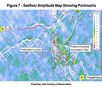
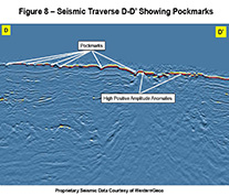
seep_anomaly_pockmarks, appearing as purple dots in Figure 1, are circular to oval depressions interpreted to be created by the removal of sediment through rapid, and possibly, explosive gas expulsion. Few pockmarks have visible active migration pathways on vertical seismic profiles, but most appear to be dormant and without discernible active migration. Rapid expulsion is interpreted to be exclusively gas and appear to be purely destructive due to the removal of sediment. No sediment, brine, or oil expulsion has been observed during direct observations. Due to a lack of hard substrate and absence of continuing seepage at most pockmarks, chemosynthetic organisms and corals are unlikely to be associated with them. Figure 7 is an amplitude map of an area with numerous pockmarks. Figure 8 is a vertical seismic profile (D-D’) showing the pockmarks on the seafloor. The pockmarks on the Florida Shelf are actually sinkholes created by underlying karstic formations.
- Water-Column Gas Plumes Class
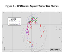 Detected by NOAA’s RV Okeanos Explorer during cruises in 2011, 2012, and 2014, this class represents plumes of gas found in the water column, originating from seafloor seeps, as detected by EK60 single beam sonar and the EM302 multibeam sonar. Due to the relatively similar acoustic properties of oil and water, these sonars are unable to discern if oil seepage is associated with any of these gas plume sites. We are including the files of both the EK60 and EM302, as they have different swath widths of detection (EK 60 is around 20-60 feet depending on water depth, and the EM 302 is 3.7 times the water depth); see Figure 9. Many of these plumes helped confirm BOEM seep-related anomaly polygons included in the shapefiles below. Updates of the Okeanos Explorer 2014 cruise, as well as other sonar surveys by other vessels will be made in the future. The two shapefiles are called:
- plumes_EK60_points – Points with a triangle symbol. Low uncertainty of seep location.
- plumes_EM302_400ft_diam – These are downloaded as 400 foot diameter circles to indicate the uncertainty of the exact seep location on the seafloor, which varies with water depth. You will note many of the circles are clumped nearby each other. Due to the nature of overlapping swath data acquisition, some of those clumps may actually represent a single seep from the same spot on the seafloor; some are near the center of the swath (most accurate) and some well away from the center of the swath (less accurate). This is why there is a 400 foot diameter of uncertainty.
- seep_ anomaly_high_ positives_confirmed_gas - are high positive anomalies that have either EK 60 and/ or EM302 gas plumes identified, to originate from within the anomaly polygon
- seep_ anomaly_negatives_confirmed_gas - are low positive/negative anomalies that have either EK 60 and/ or EM302 gas plumes identified, to originate from within the anomaly polygon
Non-Seep-Related Anomalies
The anomalies described below are non-seep related, and with the exception of the two Cretaceous types, all are not likely to support benthic organisms.
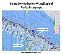
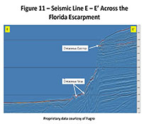
- anomaly_Cretaceous, outlined in blue in Figure 1 and directly following the northern Florida Escarpment are long, linear high-positive amplitude anomalies extend along the face of the escarpment and, from several dives with manned submersibles and ROVs, have been found to be outcrops of Cretaceous-aged, well-indurated carbonate stratum. Each dive has proven these locations act as prime substrate for coral communities. Seismic data and paleontological data from well control on the Florida Platform establish the Cretaceous age of these rocks. The polygons in the anomaly_Cretaceous shapefiles are those mapped on 3-D seismic data; though there are 2-D data sets to the south along the escarpment, they are not amplitude balanced and were not used to develop this shapefile data set. Figure 10 is a bathymetry/amplitude map across the Florida Escarpment with the Cretaceous carbonate outcrops outlined in blue. Figure 11 is a seismic traverse (E-E’) across the escarpment.
- anomaly_Cretaceous_talus are areas along the lower Florida Escarpment with high positive amplitude response concentrated in valleys between discrete ridges that appear to be slump deposits of carbonates likely of Cretaceous age. Since the Cretaceous carbonates along the steep slopes of the Escarpment have been shown to be good substrates for coral communities, it is likely that these talus deposits would support coral communities as well. Though chemosynthetic organisms have been seen at the base of the Escarpment by ROV and submersible dives, none of the talus deposits have been visited to our knowledge and the Okeanos Explorer’s multibeam did not detect any active water column gas plumes in the mapped area. Figure 10 and Figure 11 show the talus deposits in dark blue.
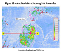
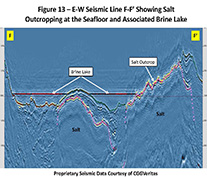
anomaly_salt, have been outlined with a unique class of large, light pink polygons in Figure 1 to distinguish them from authigenic seep carbonates. They are areas in the Gulf of Mexico where salt outcrops on the seafloor and has a very similar high-positive amplitude response as hardground seep anomalies, but from vertical seismic profiles it’s clear that salt is outcropping and these are not seep related anomalies. Two of these have been visited by the Alvin manned submersible and confirmed to be salt outcrops. Figure 12 shows three of these areas on the seafloor and the E-W seismic profile (F-F’) in Figure 13 shows one of these where the Alvin found salt on the surface.
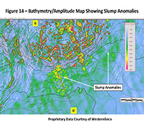
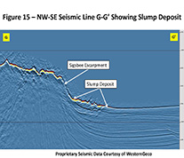
anomaly_slump are located at the base of over-steepened slopes caused by shallow vertical and horizontal salt movement; surface sediments become unstable and flow downslope to rest on low-slope seafloor in front of the steep slopes. Figure 14 is an example of interpreted slumps in front of the Sigsbee Escarpment where lateral movement of shallow salt appears to have over-steepened the seafloor, causing mass flow of sediment, leaving a slump deposit in front and a scar on the Sigsbee Escarpment. The high-positive amplitude of the slump is interpreted to be the result of winnowing of fines from the slump sediments, leaving a sand rich layer on the basin floor and/or the presence of authigenic carbonate debris that accompanied the flow. Figure 15 is a vertical seismic profile (G-G’) showing the slump deposit.
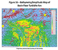
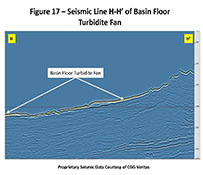
- anomaly_fan, yellow polygons with dotted fill in Figure 1, are interpreted to be sand-rich turbidite fans which have intermittently dominated sedimentation in portions of the deep water Gulf of Mexico for millions of years and are the source of many of the subsurface sand reservoirs throughout the basin. There are a few large, discrete recent channel/fan complexes on the seafloor (especially in Alaminos Canyon) that have high-positive acoustic response on seismic data and are easily recognized (see Figure 16) on amplitude maps. These recent examples are good analogues of reservoir geometries for subsurface exploration/development activities. Figure 17 is seismic profile H-H’ illustrating the channel and resulting basin-fill fan.
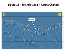
anomaly_channel polygons represent erosional, deep sea channels associated with turbidite fans (basin floor fans and basin fill fans), as well as major and minor shelf-slope-break bypass downcutting from recent lowstands. They are easily distinguished by their long, narrow, often sinuous character on amplitude and bathymetry displays. Figure 18 is seismic profile I-I’ illustrating the channel on a basin floor fan complex.
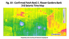
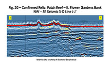
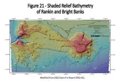
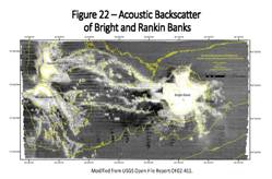
- anomaly_relic patch reefs_and _confirmed relic patch reefs are small circular positive anomalies in 100 to 350 feet of water that are common in the region of the lower shelf near or next to the coral bio-banks of the northern Gulf of Mexico (East and West Flower Garden Banks, Rankin and Bright Banks, Stetson Bank, etc.). They appear similar to mud volcanoes in size and shape, but are generally acoustically hard and do not show any indication of subsurface migration to the features. Recent multibeam mapping by the USGS show high positive acoustic backscatter also suggesting hard surface. The confirmed relic patch reefs have had direct observation of present day live bottom communities by ROV deployments. We are hypothesizing that their origins were as relic patch reefs during past low sea-level stands because of their water depths, size and shape, and hard surfaces. Figure 19 is a 3-D time migrated map of three confirmed patch and Figure 20 is a NW_SE seismic traverse J-J’ through them. Figure 21 is a multibeam bathymetry map acquired by USGS over the Rankin and Bright Banks and Figure 22 is the acoustic backscatter derived from that multibeam showing the high positive backscatter.
File Details:
These files were generated using ESRI® ArcGIS ArcMap™ 10.5 in a Microsoft® Windows® 10 operating system, and have been tested to be backwards compatible through version 9.3.1.
Datum Information: These files have the GCS_North_American_1927 coordinate system, datum D_North_American_1927, spheroid Clarke_1866. Linear units are Foot_US.
File formats: For your convenience, the anomaly files have been provided in Layer Package Format (.lpk), which is similar to a zipped folder. The single file contains all 23 anomaly types, metadata, coordinate information, and visual symbology. Alternatively, if you would rather download each type of anomaly individually, you may do so with the individual zipped folders below. The individual zipped folders contain the standard shapefile suite of files (.shp, .dbf, .prj, etc.) and also a layer file (.lyr) which contains the visual attributes and descriptions of each shapefile. We have also made .DWG files available for CAD users. The DWG files are in R2010 format.
Instructions to View the Anomaly Polygons:
If using ESRI® ArcGIS ArcMap™ 9.3.1 or later
NOTE: Methods 1 and 2 below are totally dependent on the internal settings of your ArcGIS File Handler application, commonly located at C:\Program Files (x86)\Common Files\ArcGIS\bin\ArcGISFileHandler.exe. Launch your ArcGISFileHandler to specify where and how GIS data packages are extracted if you encounter errors opening these files.
Method 1: Layer Package file with ArcMap™ already running
- Download the Layer Package file (.lpk)
BOEM Seafloor Anomalies Layer Package (June 2019) (If you have problems downloading, try right-clicking and saving.)
- Open the ArcMap™ project you will be using.
- Using Windows Explorer or ArcCatalog™, navigate to the downloaded .lpk file and open it.
- The files will be unpacked and loaded to your project automatically. Note - Unpacking may take minutes.
Method 2: Layer Package file with ArcMap™ not already running
- Download the Layer Package file (.lpk)
BOEM Seafloor Anomalies Layer Package (June 2019) (If you have problems downloading, try right-clicking and saving.)
- Using Windows Explorer or ArcCatalog™, navigate to the downloaded .lpk file and open it.
- The file will automatically launch ArcMap™ and unpack the files to a blank project. Note - Unpacking may take minutes.
Method 3: (not recommended) Loading individual shapefiles instead of the Layer Package file
- Download the desired individual anomaly zip files from below.
- Unzip/extract the files, ensuring you keep the shapefile suite files together for any given anomaly type. The shapefiles will not display correctly if separated from each other or from their layer .lyr files!
- Open the ArcMap™ project you will be using.
- Within ArcMap™ launch ArcCatalog™, for each anomaly type you would like to load into your project, click and drag its layer .lyr file into your map first. DO NOT drag the shapefile (.shp) into your map first unless you want to strip the file of all formatting, descriptions, and metadata! Once you have imported the Layer files, the polygons will still not be visible on your map and you will have a red [ !] next to each layer. Proceed to step 5.
- After importing the Layer files, one-by-one right-click on each layer in your ArcMap Table of Contents, select “Data” and then “Repair Data Source”. Now is when you will select the corresponding shapefile.shp for each anomaly type. The polygons should now be displayed on your map, and with the preferred formatting.
Total anomaly counts as of June 2019: 36,889
- seep_anomaly_positives – 20,564
- seep_anomaly_positives_confirmed_oil – 58
- seep_anomaly_positives_possible_oil – 2,852
- seep anomaly positives confirmed gas - 92
- seep_anomaly_negatives – 1,616
- seep_anomaly_negatives_confirmed_oil – 32
- seep_anomaly_negatives_possible_oil – 477
- seep anomaly negatives confirmed gas - 58
- seep_anomaly_confirmed_organisms – 286
- seep_anomaly_confirmed_corals – 54
- seep_anomaly_confirmed_hydrate – 2
- seep_anomaly_flows – 694
- seep_anomaly_confirmed_carbonate – 179
- seep_anomaly_confirmed_buried_carbonate – 404
- seep_anomaly_mud_volcanoes – 793
- seep_anomaly_confirmed_mud_volcanoes – 59
- seep_anomaly_pockmarks – 4,918
- anomaly_Cretaceous – 326
- anomaly_Cretaceous_talus - 190
- anomaly_salt – 141
- anomaly_slumps – 318
- anomaly_fans – 34
- anomaly_channels - 127
- anomaly_relic_patchreefs - 1,471
- anomaly_confirmed_relic_patchreefs - 74
- plumes_EK60_points – 115
- plumes_EM302_400ft_diam – 865 - EM302 anomalies were detected, but many are duplicates due to the geometry and nature of the multibeam swath and overlapping traverses over the same area. The more accurate number of seep sites represented by this file is estimated to be 400-450.
- states - Outline of continental United States
IMPORTANT LAYER PACK FILE LOADING TIME NOTICE:
When initially loading the Layer Package file to your project, please use patience. There are over 32,000 polygons in the files, so they may take up to a few minutes to load in to your project. Your project may freeze temporarily while the file is being unpacked.
If using any other GIS software
- Download the desired individual anomaly zip files from directly above by clicking on its name.
- Unzip/extract the files, ensuring you keep the shapefile suite of files together for each given anomaly type. The shapefiles will not display correctly if separated from each other!
- Open your GIS project and load the shapefiles.
If using CAD software
- Download the zipped folder BOEM Seafloor Anomalies DWG Format (June 2019).
- Unzip/extract the .DWG files.
- Open your CAD project and import the .DWG files.
You can assist in making this database more complete!
A significant limiting element in this dataset is our lack of knowledge of all the sites in the Gulf of Mexico that have been confirmed by direct observations. Should you discover through your use of these files, that you may have evidence to confirm the presence or absence of chemosynthetic and/or coral communities, hydrates, oil & gas seeps, etc., BOEM asks that you to contact via email GeohazardGOMR@boem.gov with lat/longs, maps, photos/videos, etc., so we can update our database for the benefit of all using this resource. This website will be referencing the source of these confirmations known to date and will give credit to all who contribute information in the future.
BOEM wants to thank the following companies for allowing the use of their data in generating and publishing these derivative interpretations:
- WesternGeco, LLC
- TGS
- CGG Services (U.S.) Inc., Houston, TX.
- PGS
- Seitel
- Geophysical Pursuit
- Exxon


